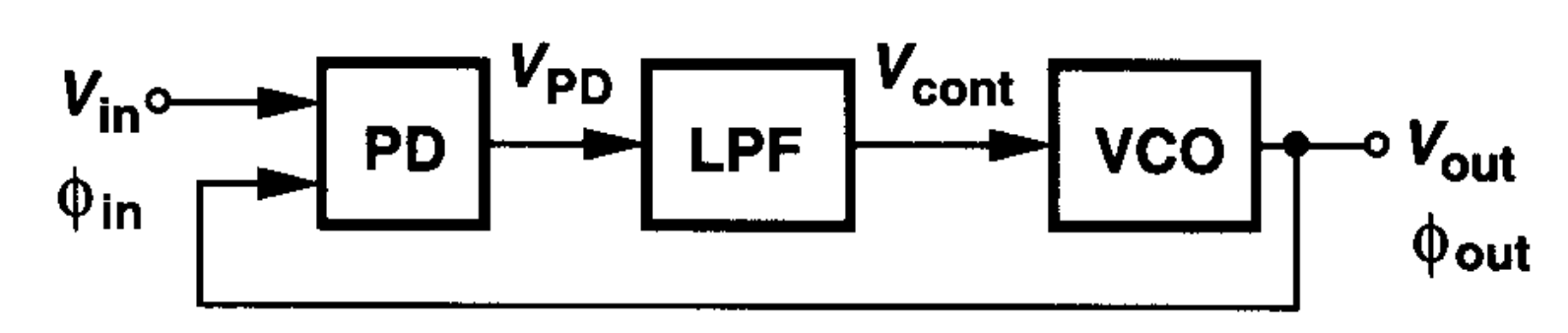
Type I PLL Topology
原理图
-
Phase Locking: Align the Output Phase of VCO and Phase of the reference
-
用LPF除去AC Signal,保留DC signal
-
为了定义Phase Lock Condition, 我们需要使得$\phi_{out} - \phi_{in}$ 保持不变, 也就是
$$ \begin{aligned} \frac{d\phi_{out}}{dt} - \frac{d\phi_{in}}{\phi_{in}} &= 0 \\ \omega_{out} &= \omega_{in} \end{aligned} $$
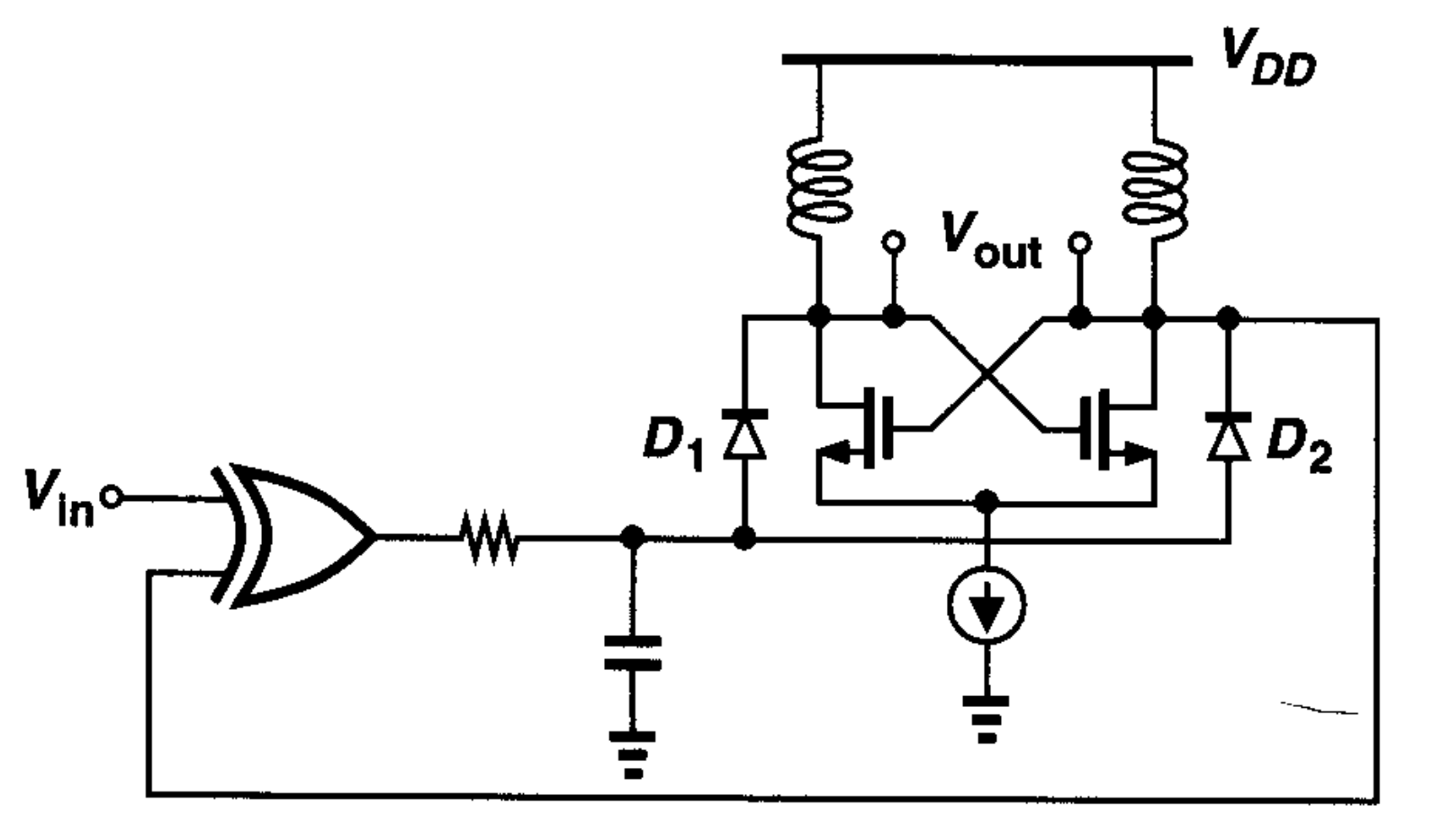
一个简单的PLL
-
用XOR作PD
-
用LC电路作LPF
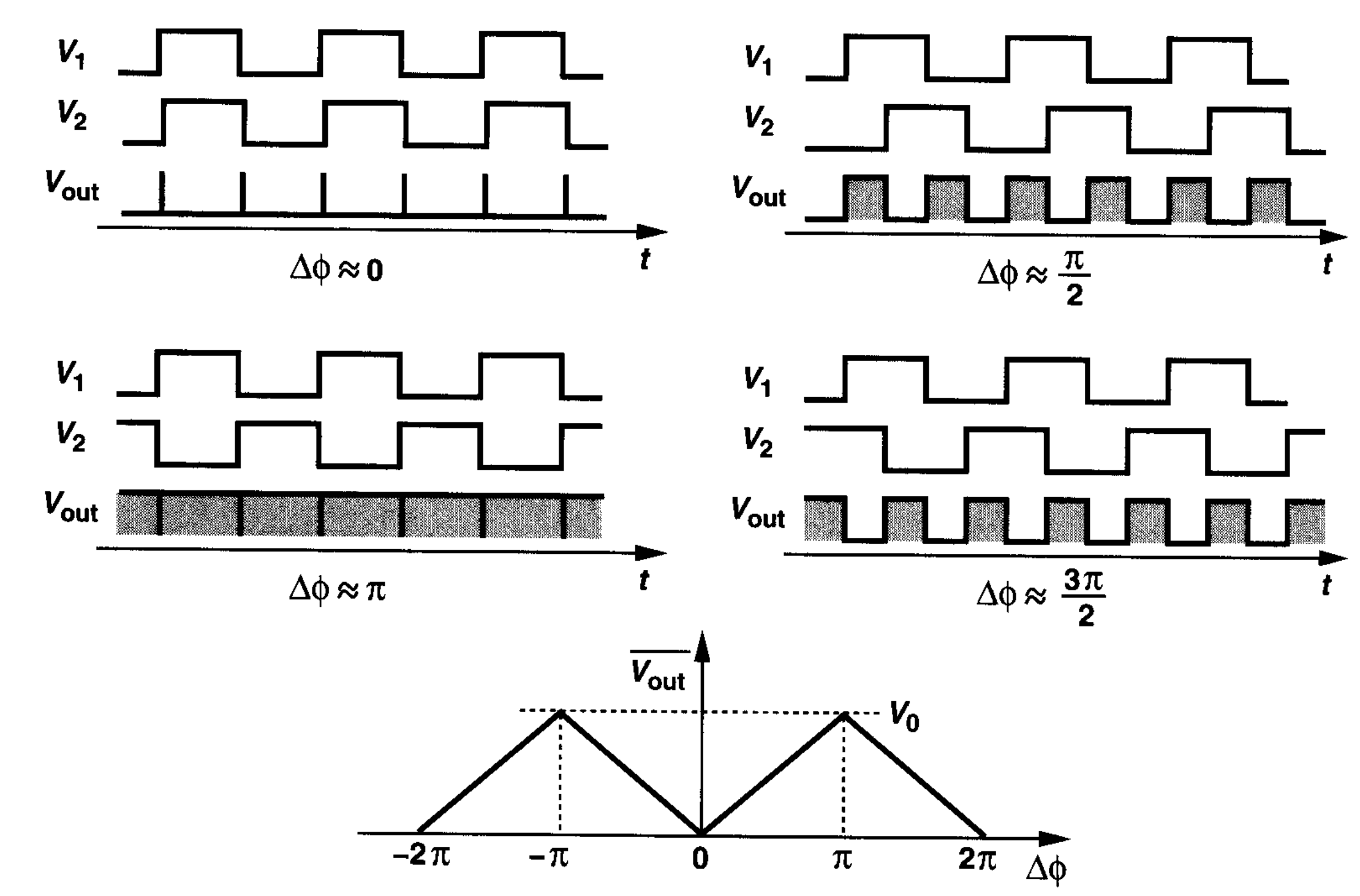
Phase Detector
I/O关系
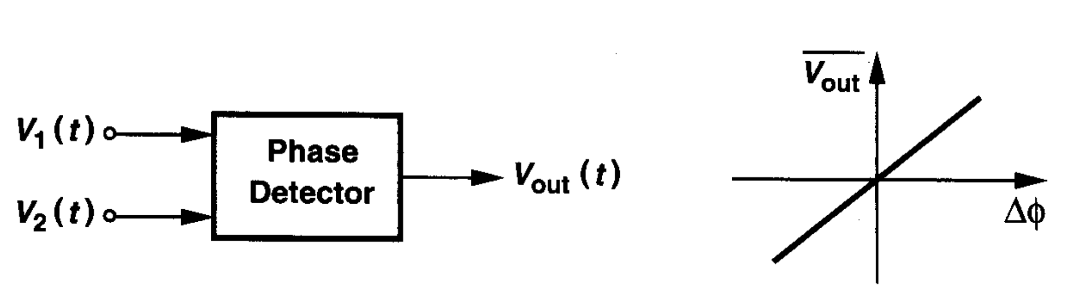
$$ \begin{aligned} \overline{V_{out}} &= K_{PD}\Delta \phi \\ Gain &= K_{PD} \end{aligned} $$
- $K_{PD}$单位为$V/rad$
实现方式
通过XOR实现Phase Detect
- 电路和时序图
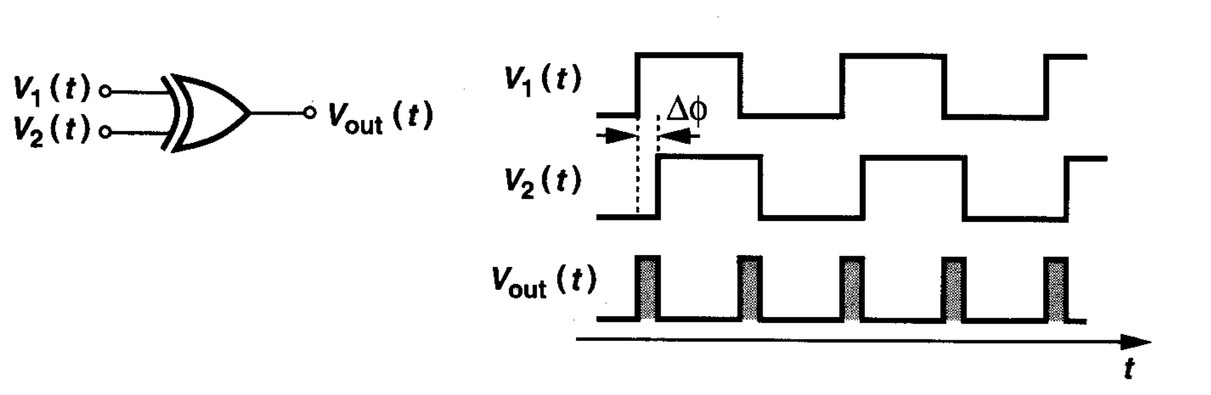
- 不同相位差下的时序图和输出电压变化
PFD (Phase/Frequency Detector)
- 操作
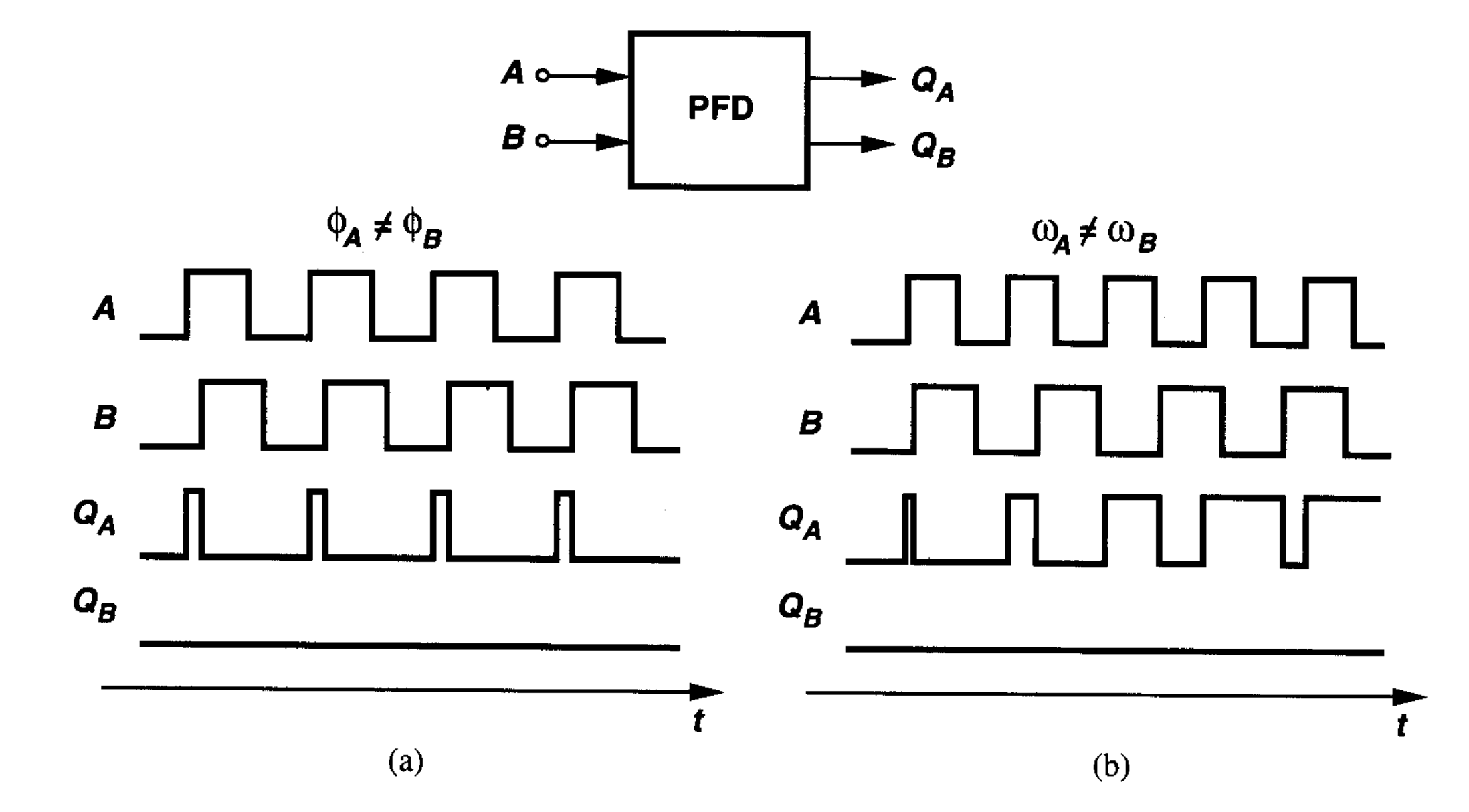
| $Q_A$ | $Q_B$ |
|---|---|
| UP Pulses | Down Pulses |
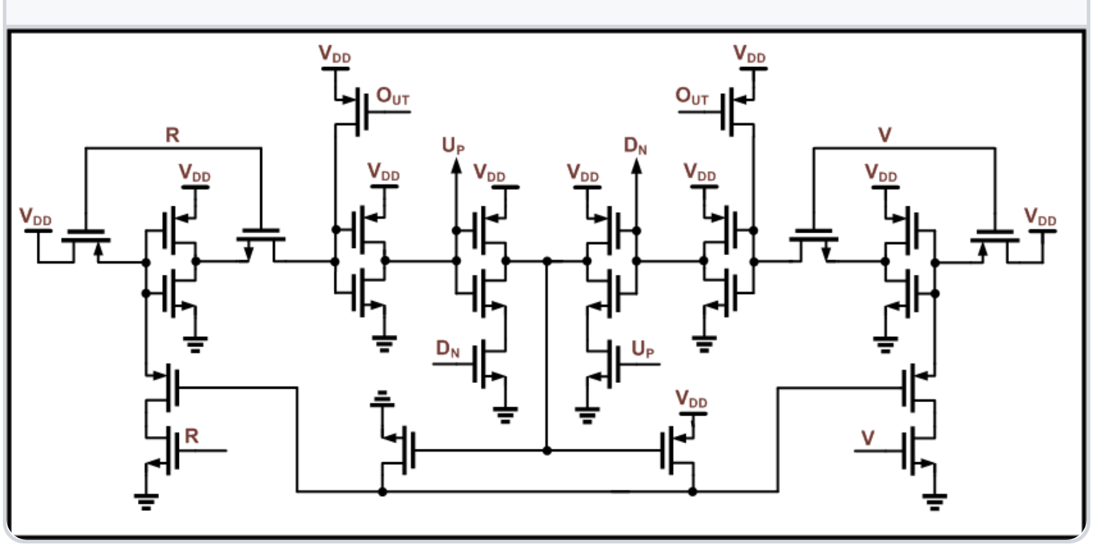
电路图
- 总体结构
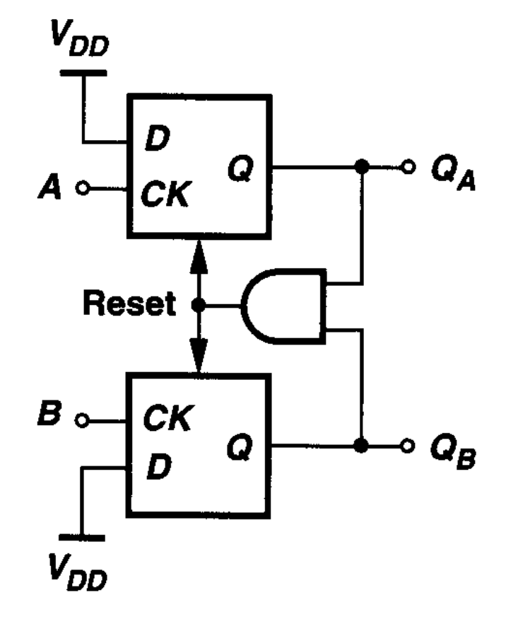
- 门电路
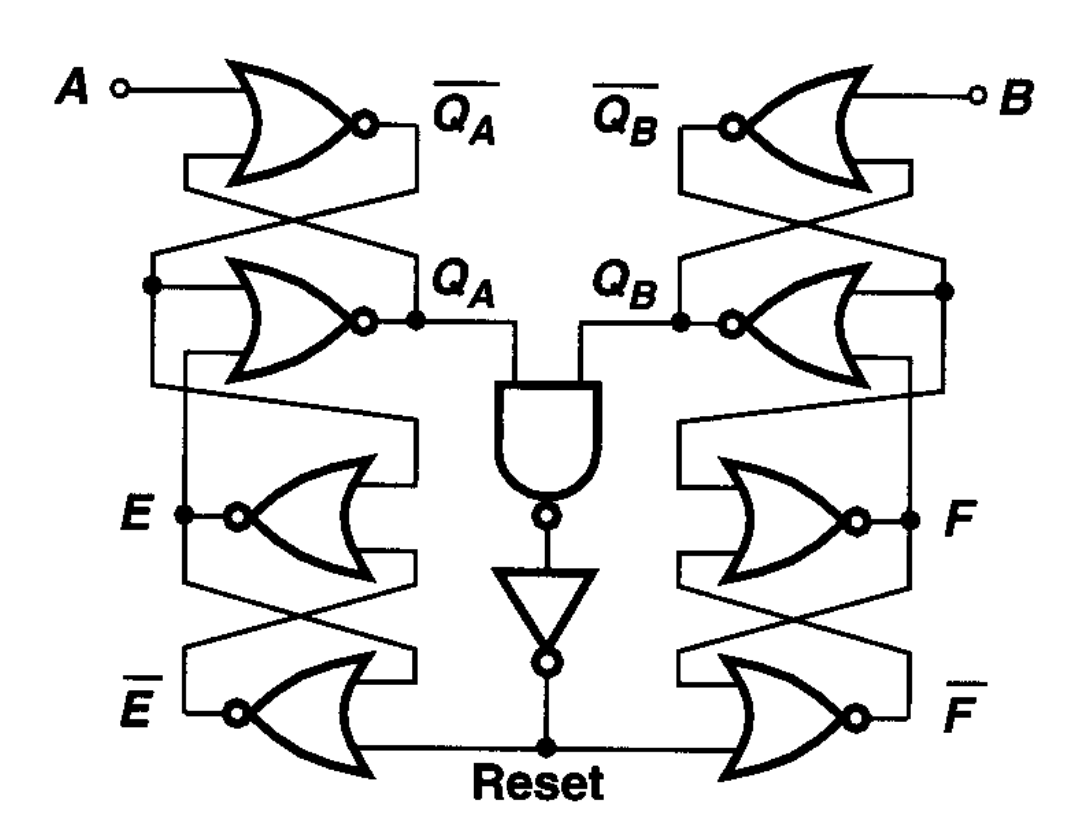
- CMOS电路
效果
- 当频率很低时,就成了一个PD
Charge Pump
结构图
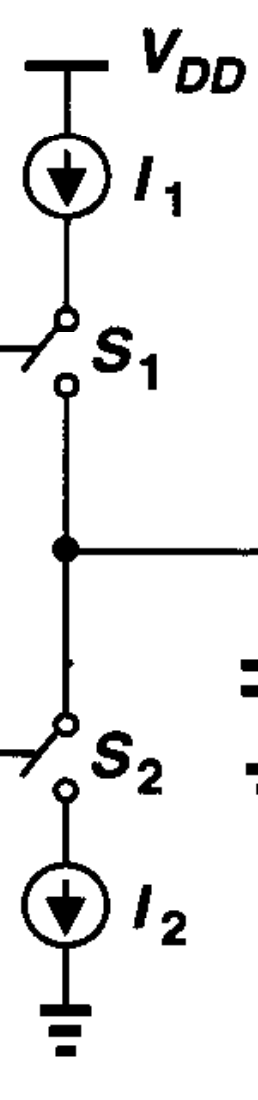
优化
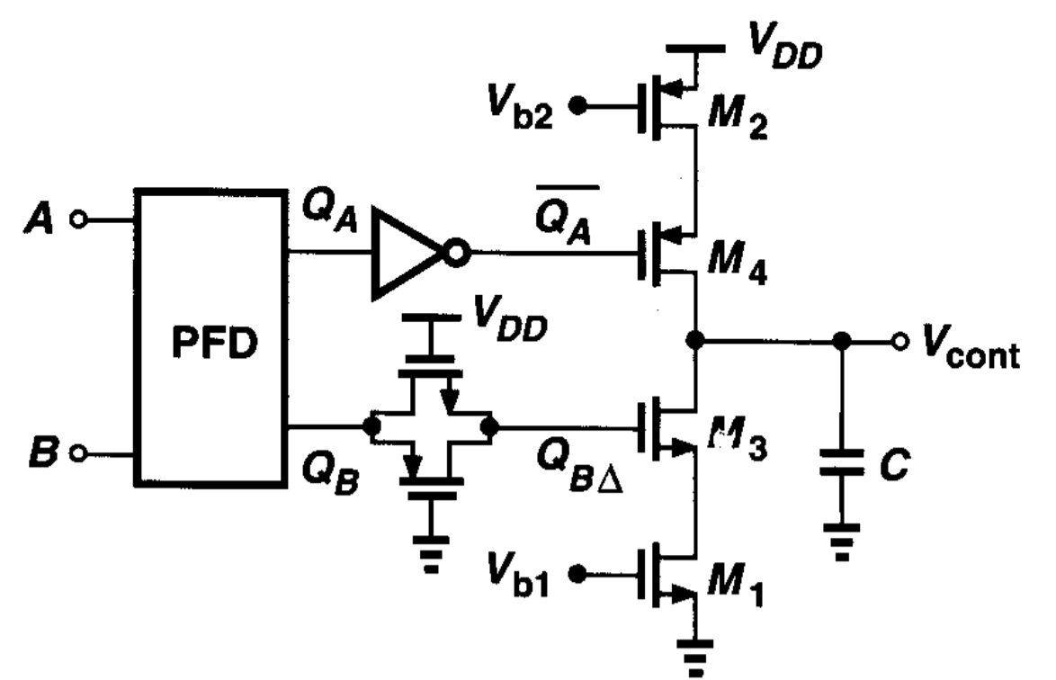
-
用MOSFET做电流源和开关
-
用一个CMOS Pass Gate来达到与$Q_A$相同的delay
Dynamics of CPPLL
Is it a Linear System?
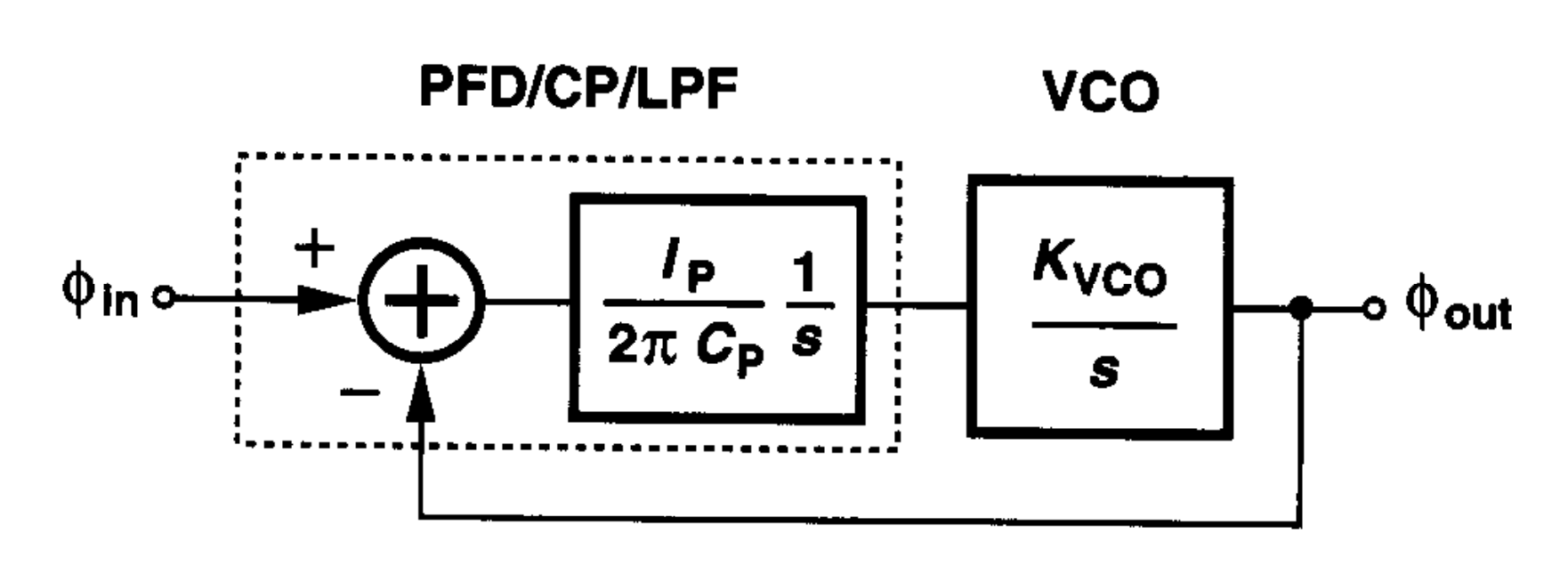
Transfer Function of PDF/CP/LPF
- Step Response of PDF/CP/LPF
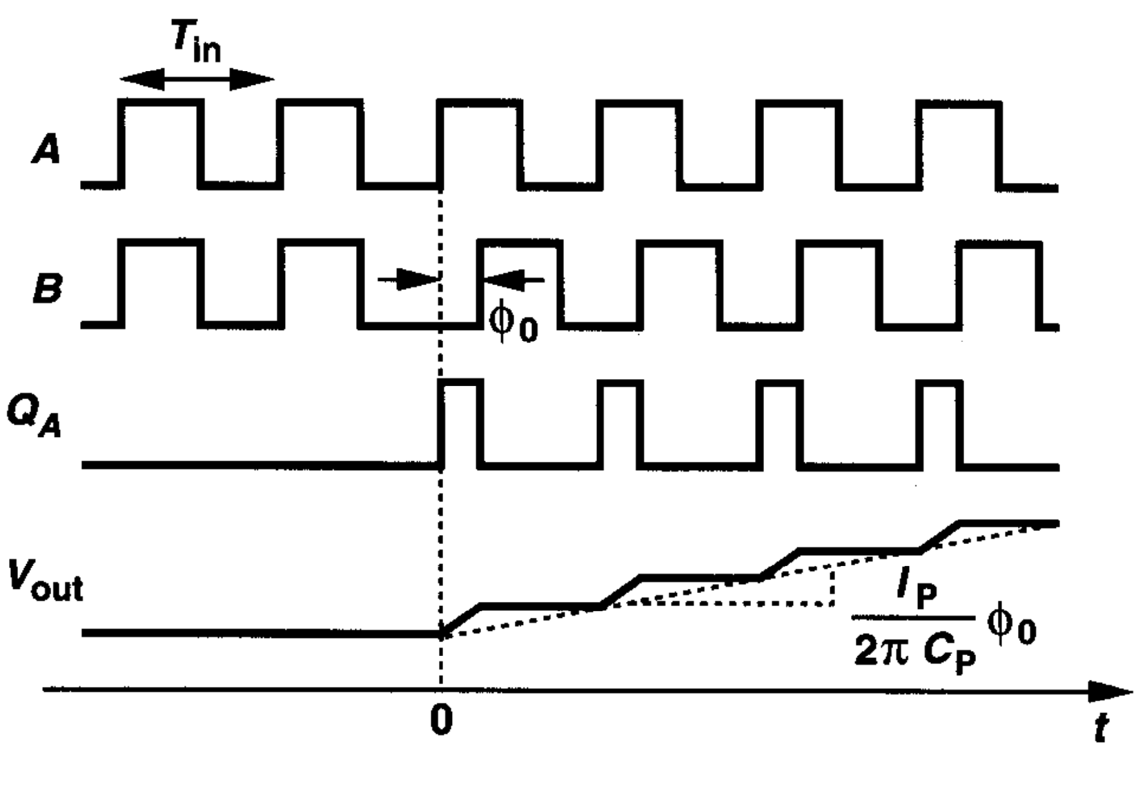
-
$I_P$为CP电流
-
$C_P$为LPF的电容
- Transfer Function
$$ \begin{aligned} V_{out}(t) &= \frac{I_P}{2\pi C_P} t \Delta \phi u(t) \\ \therefore h(t) &= \frac{I_P}{2\pi C_P} u(t) \\ \therefore H(s) &= \frac{V_{out}(t)}{\Delta \phi}(s) \\ &= \frac{I_P}{2\pi C_P} \cdot \frac{1}{s} \end{aligned} $$
Simple CPPLL
原理图
电路图
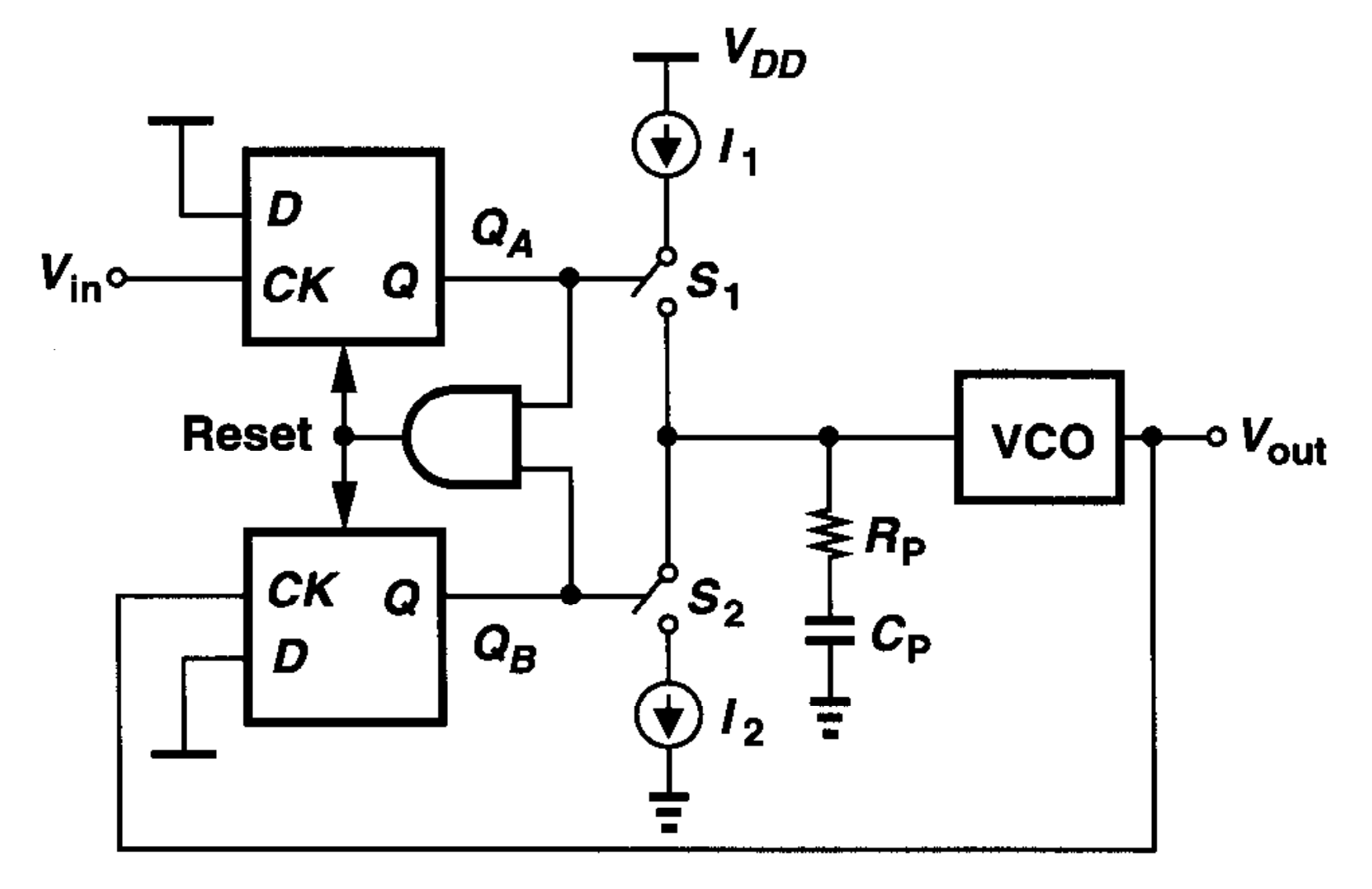
分析
- 为了稳定电路,增加了一个$R_P$
$$ \begin{aligned} \frac{\Phi_{out}}{\Phi_{in}}(s)|{open} &= \frac{I_P}{2\pi} ({\frac{1}{sC_P} + R_P}) \frac{K{VCO}}{s} \\ \therefore H(s) &= \end{aligned} $$
优化
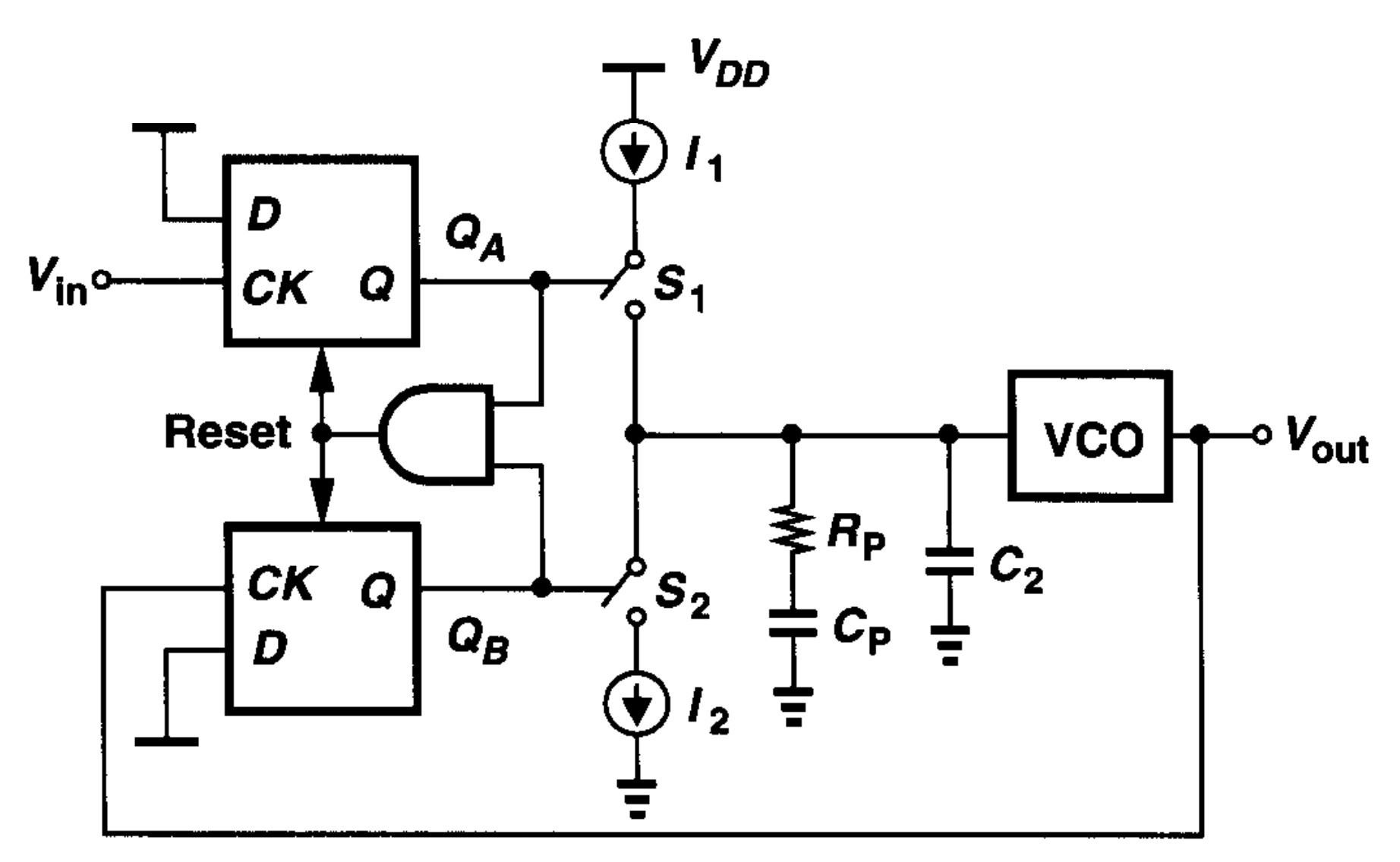
- 增加一个$C_2$以减小Ripple
附录
Gain Crossover
增益(Gain)曲线和相位(Phase)曲线相交的位置